| Prev | Next |
Configure SysML Simulation
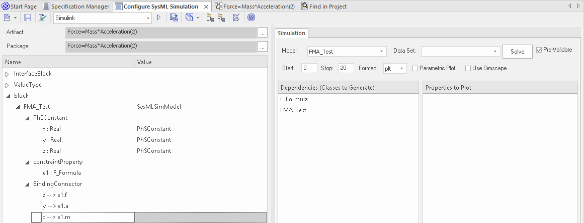
The Configure SysML Simulation window is the interface through which you can provide run-time parameters for executing the simulation of a SysML model. The simulation is based on a simulation configuration defined in a SysMLSimConfiguration Artifact element.
Access
|
Ribbon |
Simulate > System Behavior > Modelica/Simulink > SysMLSim Configuration Manager |
|
Other |
Double-click on an Artifact with the SysMLSimConfiguration stereotype. |
Toolbar Options
Option |
Description |
See also |
|---|---|---|

|
Click on the drop-down arrow and select from these options:
|
|

|
Click on this button to save the configuration to the current Artifact. |
|

|
Click on this icon to specifically validate the model against the SysML configuration now. The results of the validation display in the 'SysML Simulation' tab of the System Output window. You can also select an option to automatically pre-validate the model before each simulation is executed. See the 'Pre-validate' option in the Simulation Tab table. |
|

|
Click on this icon to expand every item in the hierarchy in the 'Name' column of the window. |
|

|
Click on this icon to collapse all the expanded items in the model hierarchy in the 'Name' column of the window. |
|

|
Click on this icon to display a list of object types that can be suppressed in the simulation. Click on the checkbox against each object to suppress, or click on the to select all items for suppression. You can also use the Bar at the top of the 'Option' column to only display items having the specified letter or text string in the name. |
|
|
text field |
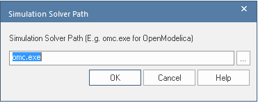
Click on the drop-down arrow and select the application under which the simulation is being run - such as OpenModelica or Simulink. |
|

|
Click on this button to generate, compile and run the current configuration, and display the results. |
|

|
After simulation, the result file is generated in either plt, mat or csv format. That is, with the filename:
Click on this button to specify a directory into which Enterprise Architect will copy the result file. |
|

|
Click on this button to select from these options:
|
Simulation Artifact and Model Selection
Field |
Action |
See also |
|---|---|---|
|
Artifact |
Click on the |
Select |
|
Package |
If you have specified an existing SysMLSimConfiguration Artifact, this field defaults to the Package containing the SysML model associated with that Artifact. Otherwise, click on the |
Package Objects
This table discusses the types of object from the SysML model that will be listed under the 'Name' column in the Configure SysML Simulation window, to be processed in the simulation. Each object type expands to list the named objects of that type, and the properties of each object that require configuration in the 'Value' column.
Many levels of the object types, names and properties do not require configuration, so the corresponding 'Value' field does not accept input. Where input is appropriate and accepted, a drop-down arrow displays at the right end of the field; when you click on this arrow a short list of possible values displays for selection. Certain values (such as 'SimVariable' for a Part) add further layers of parameters and properties, where you click on the  button to, again, select and set values for the parameters. For datasets, the input dialog allows you to type in or import values, such as initial or default values; see the Model Analysis using Datasets Help topic.
Element Type |
Behavior |
See also |
|---|---|---|
|
ValueType |
ValueType elements either generalize from a primitive type or are substituted by SysMLSimReal for simulation. |
|
|
Block |
Block elements mapped to SysMLSimClass or SysMLSimModel elements support the creation of data sets. If you have defined multiple data sets in a SysMLSimClass (which can be generalized), you must identify one of them as the default (using the context menu option 'Set as Default Dataset'). As a SysMLSimModel is a possible top-level element for a simulation, and will not be generalized, if you have defined multiple datasets the dataset to use is chosen during the simulation. |
|
|
Properties |
The preferred way to specify constants or variables and their settings is to use the SysPhS stereotypes PhSConstant and PhSVariable on the Properties themselves. The PhSVariable stereotype has built-in properties for isContinuous, isConserved and changeCycle. The Properties will be listed under either PhSConstant or PhSVariable and the Value cannot be changed. It's also possible to define the settings within the Configure SysML Simulation window. In this case they will be listed under 'Properties'. Properties within a Block can be configured to be either SimConstants or SimVariables. For a SimVariable, you configure these attributes:
|
|
|
Port |
No configuration required. |
|
|
SimFunction |
Functions are created as operations in Blocks or ConstraintBlocks, stereotyped as 'SimFunction'. No configuration is required in the Configure SysML Simulation window. |
|
|
Generalization |
No configuration required. |
|
|
Binding Connector |
Binds a property to a parameter of a constraint property. No configuration required; however, if the properties are different, the system provides an option to synchronize them. |
|
|
Connector |
Connects two Ports. No configuration required in the Configure SysML Simulation window. However, you might have to configure the properties of the Port's type by determining whether the attribute isConserved should be set as 'False' (for potential properties, so that equality coupling is established) or 'True' (for flow/conserved properties, so that sum-to-zero coupling is established). |
|
|
Constraint Block |
No configuration required. |
Simulation Tab
This table describes the fields of the 'Simulation' tab on the Configure SysML Simulation window.
Field |
Action |
See also |
|---|---|---|
|
Model |
Click on the drop-down arrow and select the top-level node (a SysMLSimModel element) for the simulation. The list is populated with the names of the Blocks defined as top-level, model nodes. |
Creating a Parametric Model |
|
Data Set |
Click on the drop-down arrow and select the dataset for the selected model. |
Model Analysis using Datasets |
|
Pre-Validate |
Select this checkbox to automatically validate the model before each simulation of the model is executed. |
|
|
Start |
Type in the initial wait time before which the simulation is started, in seconds (default value is 0). |
|
|
Stop |
Type in the number of seconds for which the simulation will execute. |
|
|
Format |
Click on the drop-down arrow and select either 'plt', 'csv' or 'mat' as the format of the result file, which could potentially be used by other tools. |
|
|
Parametric Plot |
Note: With the checkbox selected, you must select two properties to plot. |
|
|
Use Simscape |
(if the selected math tool is Simulink) Select the checkbox if you also want to process the simulation in Simscape. |
|
|
Dependencies |
Lists the types that must be generated to simulate this model. |
|
|
Properties to Plot |
Provides a list of variable properties that are involved with the simulation. Select the checkbox against each property to plot. |